The tutorial will develop a new onsite wastewater system with a new building. One the site plan is developed exposure to editing and deleting information and map features is covered.
This example will follow the workflow for a System point, which includes the use of Forms to enter information and map system components.
Note: the Forms used in this exercise may differ from the Forms used by a particular Health Department. This will not impact the basic workflow, but may present different data collection fields on Forms.
To start, find an east/west oriented paved road, preferably with the lane markers visible in the imagery.
Important: the Exercise develops a site plan using a System Form that is configured for Permitting. The Permit Form will be used to add system components (Septic Tank, Drainfield). The Exercise can also be accomplished using the System Information Form if you are not using Permitting.
Map a New System Point #
Developing a new onsite wastewater system always starts by mapping a System point. The System point is used to manage all system information (Application, Permit, Septic Tank, Drainfield, etc.) under a single feature (System point).
The System point also provides the opportunity to add an onsite system using only a System point on the map. In this example, system components (Septic Tank, Drain Field, Soil Boring) and information about the components are added to the System point as table records, but they are not mapped.
Using only a System point to represent a system is ideal for mapping older site plans where the location of system components is difficult to determine, but information about those components if available on an old permit. Even if information about system components is collected on the System point and not mapped, it will be available for reports and other Insights.
1. Select Feature Editing Controls from the Main Menu to start mapping.

2. Select the System from the Create Features menu. This will open the System map tools in the side pane and change the cursor to a plus (+) on when positioned over the map.
3. Move the cursor to a location on the map that will represent the onsite system and map the System point.
Map System points either near the onsite system itself or on a house or driveway.
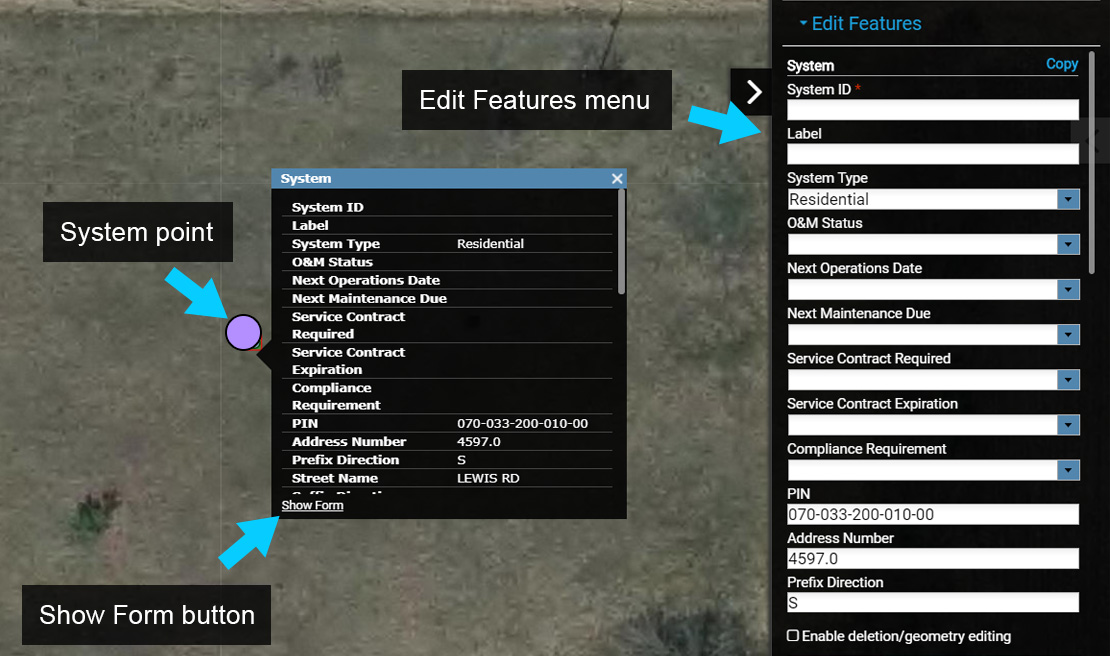
4. Next, select the ‘Show Form’ button located at the bottom left corner of the Information Window to open
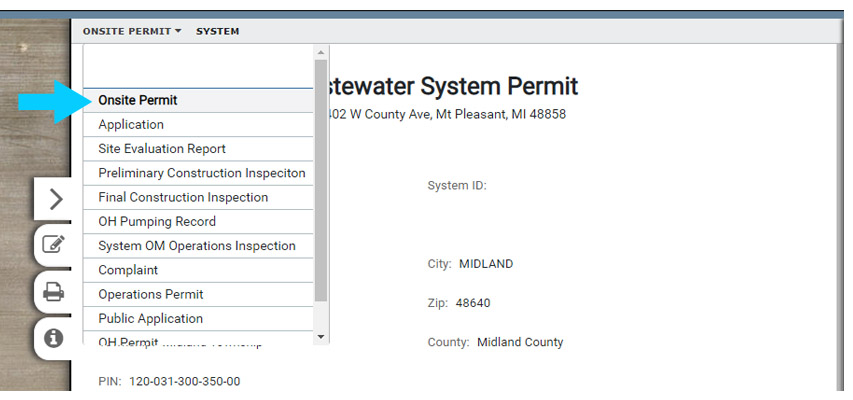
With the Form open, use the drop down menu to select the System Form that also contains a Permit (Onsite Permit in the image).
Use the System Information Form if you are not using Permitting in FetchEH.
5. Next, select the ‘Edit’ button to begin editing the Form. When the Form is in Edit mode the data entry areas will be highlighted blue.
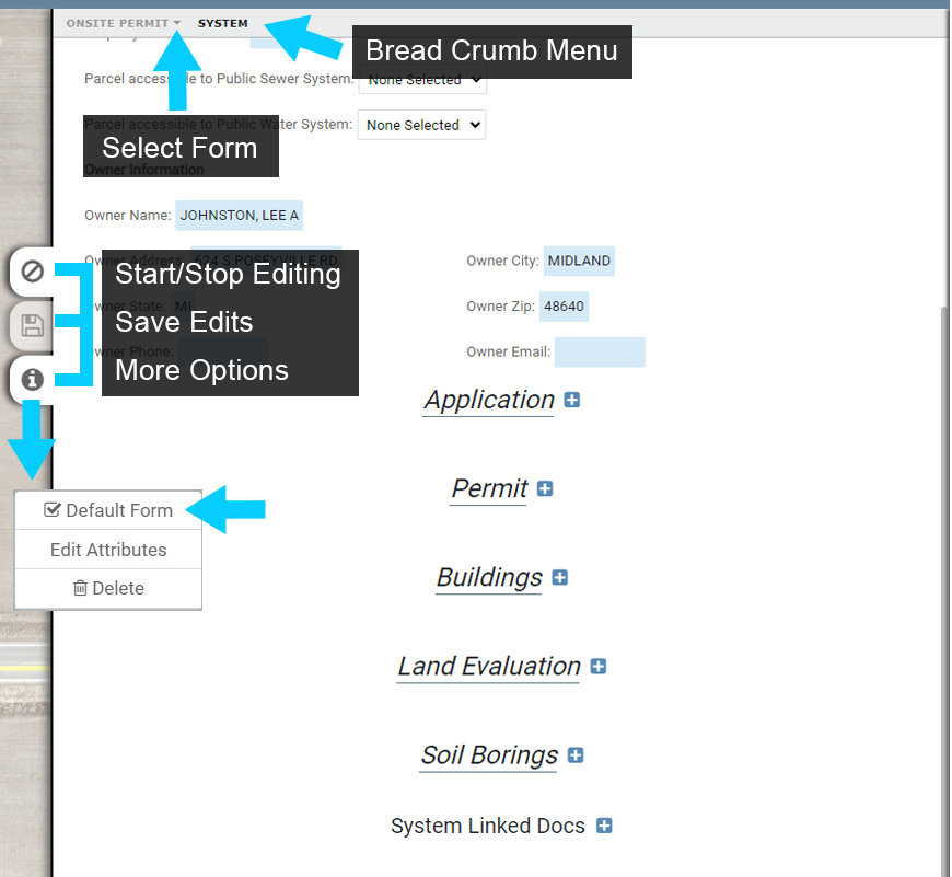
6. Make the Active Form the default Form for the current System by toggling on the ‘Default Form’ option. Setting a Form to be the Default Form means that it will always be displayed when the corresponding System point is selected.
7. Next, set the System Type to Residential, and enter any additional information for the System.
Select ‘Apply’ to save edits.
Note the Form is still in Edit mode and you could continue to Edit. However, for this exercise select ‘Close’ to end the edit session.
Overview of Adding System Components and Table Records #
The System point is a management feature that contains table records (Application, Permit, O&M Events) and mappable features (Septic Tank, Drainfield, Soil Borings). Similarly, a Restaurant contains table records for Inspections and associated Violations.
Both mappable features and table records can be added to a System a Form, in this example the Onsite Permit Form (or System Information Form if you are not using Permitting).
This section will provide an overview of how mappable features and table records are added to the System using a Form. The steps outlined in this section will be used to complete the Mapping Exercise One.
Adding Mapped Features & Table Records #
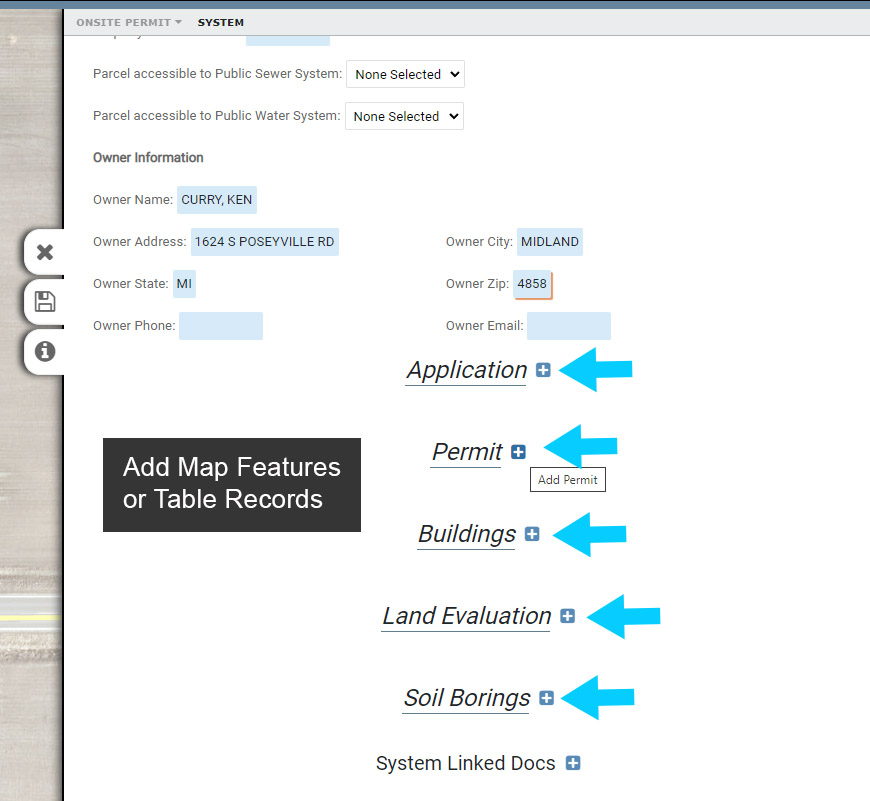
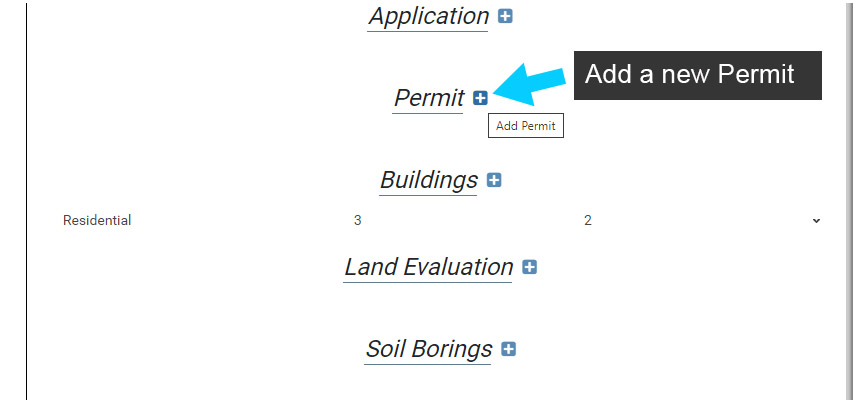
When a System point has been mapped, mappable features and table records that can be added to the System will be displayed on the active System Form (Onsite Permit here).
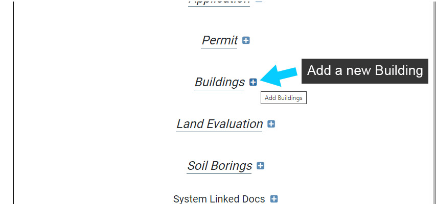
Next to the name each mappable feature (Buildings, Soil Borings in image) and table records (Application, Permit, Land Evaluation in image) is a blue (+) button. This button is used to add the corresponding mappable feature or table record to the System.
Note that you can add more than one, for example you can add two Permits to a System or multiple Soil Borings.
Adding a mappable feature to a System may also include mapping the corresponding feature (Septic Tank, Drainfield, Building, Soil Boring), but you may also add any mappable feature to a System without mapping it.
Not mapping a feature is useful when the location of the feature is unknown, but you want to take advantage of Insights.
When a mappable feature is added to a System and is not mapped, it is treated like a table record. The data about the feature is still available for Insights, but it is not available on the map for a site plan or other visual representation.
Map Measurement Lines and Control Points #
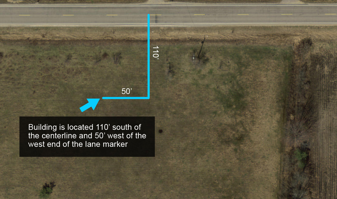
To get started with the example Site Plan we make field measurements and find the distance from the road centerline to the buildings northeast corner is 110′ south of the centerline and 50′ west of the west end of an identifiable lane marker in the road.
Before we can map the new house we first need to find the northeast corner by creating Measurement Lines that correspond with the distances we measured in the field.
1. Select the Feature Editing Controls from the Main Menu to open the Create Features menu.
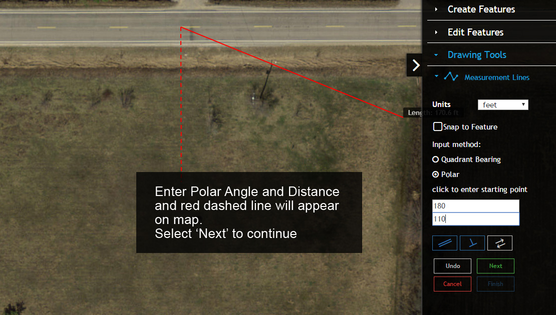
Select the Measurement Lines from the Create Features menu. This will open a new menu in the side pane and change the cursor on the map to a plus (+).
2. Move the cursor to the location on the map that represents the start of our new Measurement Line and click to start mapping (this location should be near the road centerline or near the road edge).
3. Next under Input Method select ‘Polar’ and enter 180 for the angle and 110 for distance. Since our Units are set to feet we simply need to enter 110, not 110 feet or 110′ for the distance.
4. To complete the first segment of our Measurement Line select ‘Next’.
5. Next we will continue the Measurement Line to map a second line segment that is 50′ long and extends to the west from our first line segment.
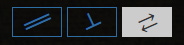
6. We could simply repeat the process we used to create the first Measurement Line segment by entering 270 degrees as our angle and 50 for distance, but we will use a different method here to become more familiar with some other mapping options in the menu.
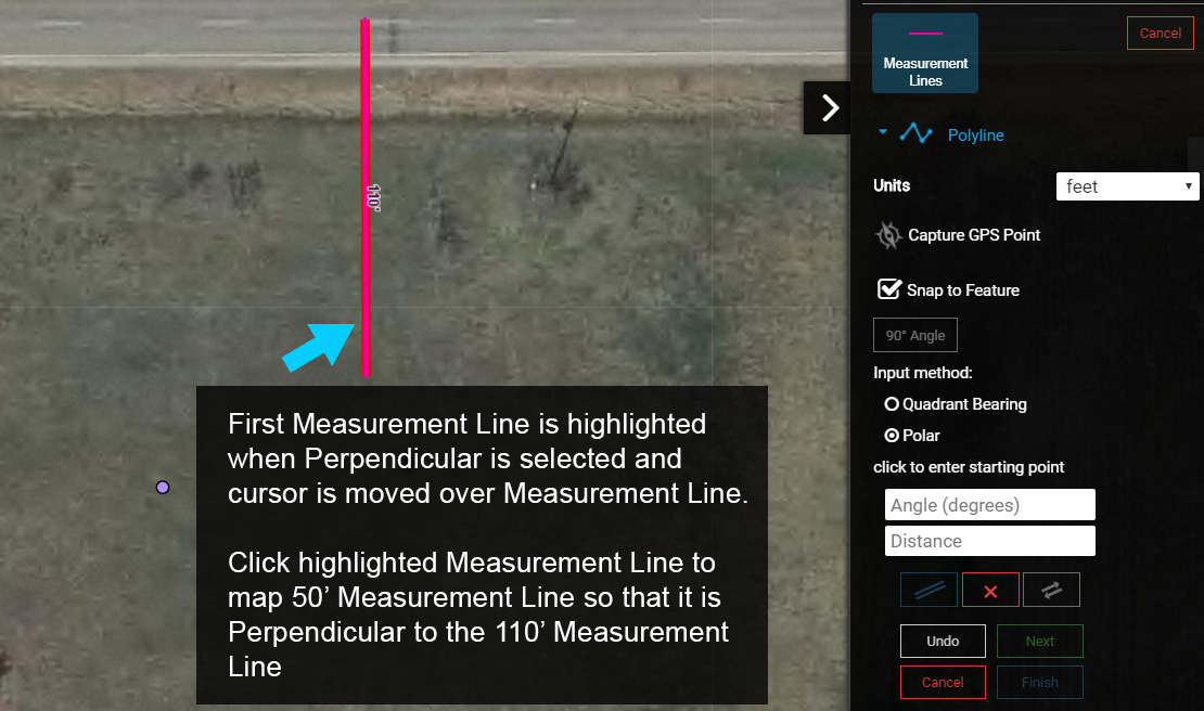
7. Toggle on the ‘Perpendicular’ option. You will notice that the first Measurement Line segment is now thicker, which means we can use it as a reference to create a second Measurement line that is perpendicular to it.

8. Next move the cursor over the first Measurement Line. Once the cursor is positioned over the Measurement Line it will be highlighted.
9. Click the highlighted Measurement Line to use it as a perpendicular reference for mapping the second Measurement Line and enter 50 for the distance.
If the new Measurement Line runs to the east rather than to the west of the first (110′) Measurement Line, use the Reverse Angle tool to change the Measurement Line direction/angle.
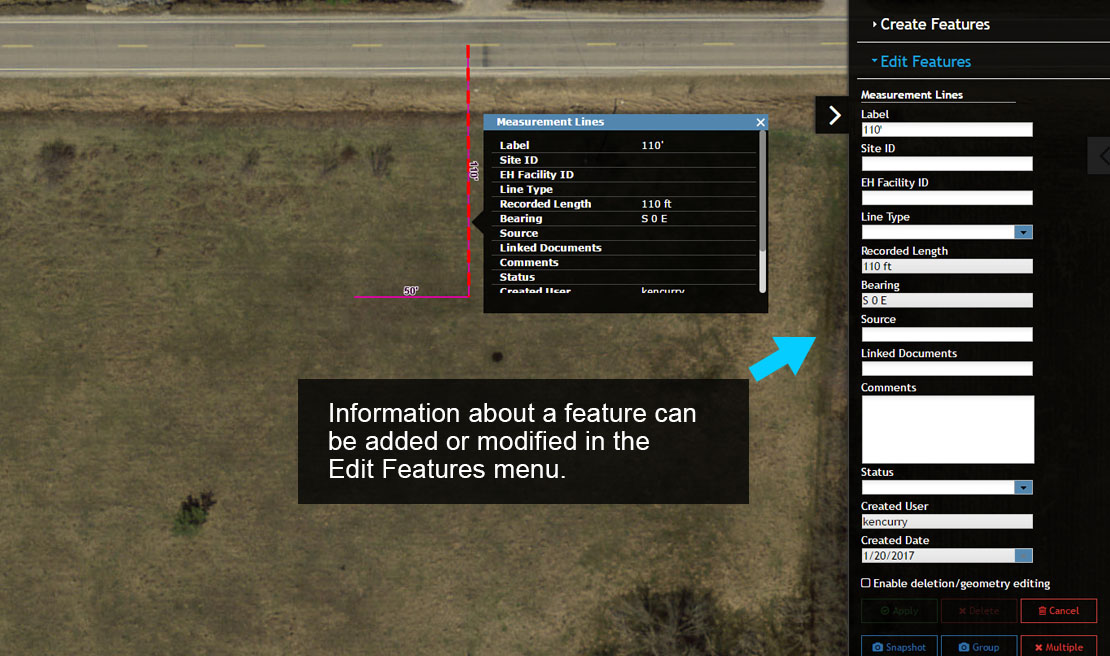
10. To finish our Measurement Lines click ‘Next’ and then ‘Finish’, which will save the features and open an Information Window and the Edit Features menu.
The Information Window and Edit Features menu displays the attribute information for the first Measurement Line (110′).
11. Using the Pan tool select each Measurement Line feature to display the corresponding Information Window. Notice that the Edit Features menu also changes to display the attributes of the selected Measurement Line feature (reference the Recorded Length input box).
Map Control Points #
1. Before the new Building is mapped, you will need to add two control points.
In this example, you will add a Benchmark at the start of the 110′ Measurement Line and an Elevation mark on a utility pole, tree or other feature visible in the imagery. If nothing obvious can be identified on the imagery add the Elevation mark in a location of your choice.
Start by selecting the Custom Point feature from the Create Features Menu.
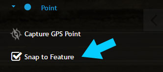
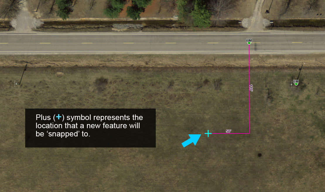
2. You will place the Benchmark at the north end of the 110′ Measurement Line, so toggle on the Snap to Feature option. This will make it easy to ‘snap’ the Benchmark to the Measurement Line.
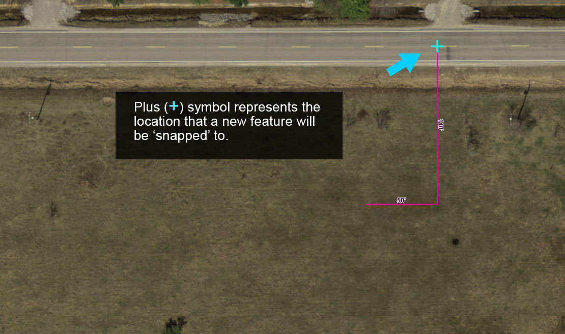
3. With the Snap to Feature option enabled, move your cursor to the start of the 110′ Measurement Line. A blue plus (+) will appear, which represents the location on the Measurement Line that the new Benchmark will be ‘snapped’ to. Click to map the Benchmark.
4. Once the Benchmark is mapped use the Edit Features menu to add the text “BM” in the ‘Note Label’ input box. Input boxes with ‘Label’ in the title are used to add a feature label on the map.
Note that the field Note Type can be used to standardize Custom Points. Using this option will create a Custom Point with a predefined symbol for consistency.
5. Next, repeat the process above for the Benchmark this time mapping an Elevation mark. You will be mapping the Elevation mark on a utility pole, tree or other area so the Snap to Feature option is not required.
Add the text “EM” in the ‘Note Label’ input box. You can also add more descriptive notes in the ‘Comments’ area when needed.
6. Select the Elevation Mark and then open the Symbol Editor menu that appears below the Navigation Menu. Select the button to expand the menu if it is not visible.
Next, change the Outline Width, Color and Size of the Elevation Mark. Select Apply to save the edits.
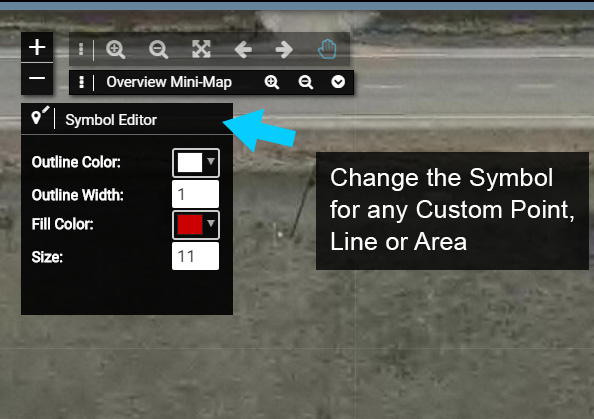
Note that any Custom Point, Line or Area symbol can be modified in this manner.
Adding the Building #
You have now successfully mapped two Control Points and two Measurement Lines, which will act as the starting point for mapping the new house.
For this example we will map a house that is 48′ west to east and 40′ north to south with the northeast corner coincident with the west end of our 50′ Measurement line.
1. To add a new Building select the System point on the map and select ‘Show Form’ in the Information Window.
2. Make sure the active Form is a Permit Form (System Information Form if not using Permitting), then select ‘Edit’ to start an edit session.
3. Scroll down the Form until the Buildings are visible, then select the ‘Add to Buildings’ button to add a new Building to the System.
4. The new Building will be added to the System and the Form will now display information that can be entered about the Building.
Enter the following information about the Building:
- Building Status: Active
- Building Class: Residential
- Number of Baths: 2
- Number of Bedrooms: 3
Save your Edits.
5. Next, add the building to the map by selecting the ‘Add to map’ button (pencil icon). This will open the Create Features > Building side pane menu.
Note, you can choose to map the Building first and then enter information about it, or not map the Building at all and only add information abouEn
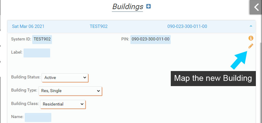
For this example you will map a house that is 48′ west to east and 40′ north to south with the northeast corner coincident with the west end of our 50′ Measurement line.
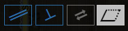
6. From the side pane, select ‘Switch to Polygon’ so you can continue to practice using some of the advanced mapping tools to map the new house.
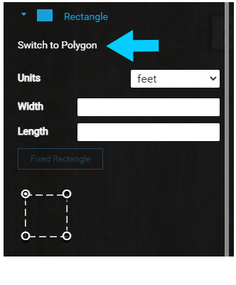
You will start mapping the new Building feature at the west end of the 50′ Measurement Line, so toggle the ‘Snap to Feature’ on to make snap the Building to the Measurement Line.
7. Move the cursor to the west end of the 50′ Measurement Line where a blue plus (+) will appear on the Measurement Line. The blue plus (+) is the location on the Measurement Line that the new Building will be ‘snapped’ to.
Note: You can ‘snap’ to points and the edge of a line or polygon.
8. Next click to ‘snap’ the starting point for the new Building to the west end of the 50′ Measurement Line.
9. The new Building could be mapped using Polar angles and distances, but in this example use the Parallel, Perpendicular and Square and Finish options.
10. Toggle the ‘Parallel’ option on and move the cursor to the 110′ Measurement Line. Click it to use that line as our ‘Parallel’ to reference.

11. The new Building is 40′ north to south, so enter 40 as the distance. If the line is displayed in the wrong direction extending north of the 50′ Measurement Line instead of south use the ‘Reverse Angle’ option to change the line direction.
12. Once the line is extending south of the 50′ Measurement Line select ‘Next’.
13. Use the ‘Parallel’ or ‘Perpendicular’ option to create the 48′ line extending to the west of the first (40′) Building line. Once the 48′ line is extending to the west of the first Building line select ‘Next’. The new Building feature now has two segments mapped and should appear displayed here.
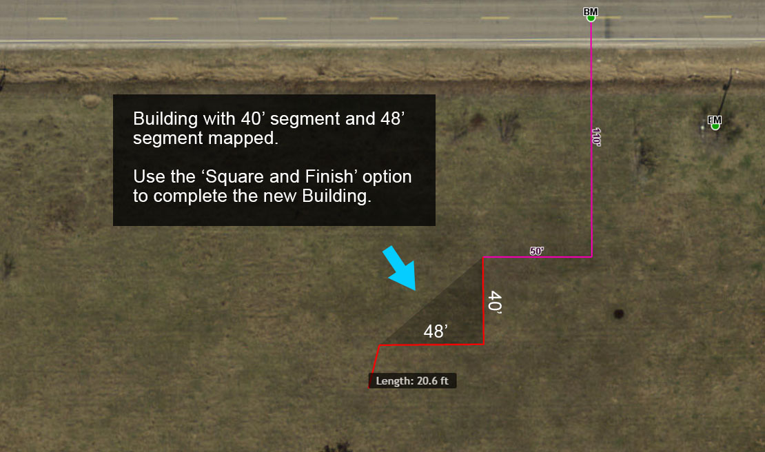
14. Now that there are two line segments of the Building mapped, you can use a shortcut to complete the new Building. Select the ‘Square and Finish’ option to complete the Building.
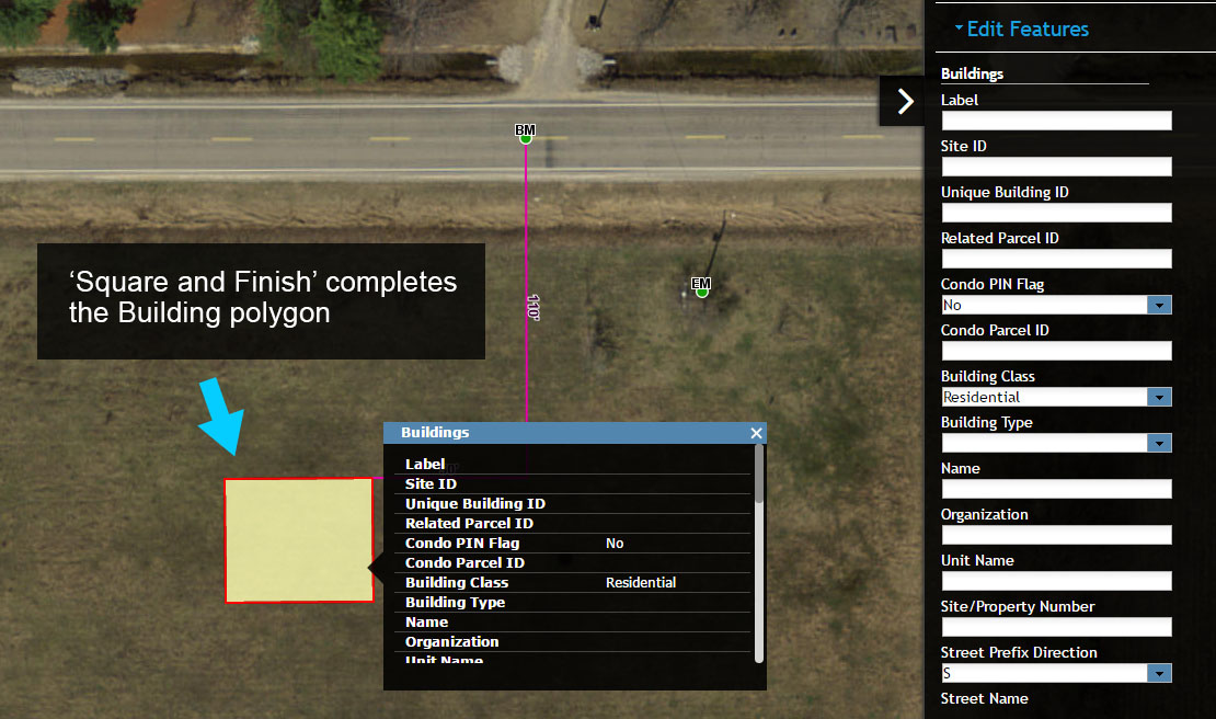
15. Once the Building is mapped, the Form will open to display the Building information. Note that the ‘Add to map’ button (pencil icon) is no longer present because the Building has been mapped.
You could add additional Buildings following the same process, but for now select ‘Close’ to end the edit session.
Adding a Septic Tank #
With the Building mapped you can begin adding and mapping the onsite system, and soil borings. You will start by adding and mapping a Septic Tank.
Start by mapping Measurement Lines as described below:
Septic Tank – the northwest corner of a 6′ by 8′ Septic Tank will be located 15′ south and 10′ east of the southwest corner of the Building. The 8′ segment of the Septic Tank will be oriented north/south.
1. Map the two Measurement Lines to locate the Septic Tank. The first Measurement Line is 15′ extending south from the southwest corner of the building, and the second Measurement Line extends east 10′ from the end of the first Measurement Line.
Use either Polar Angles, or Parallel and Perpendicular tools to map the Measurement Lines.
2. Next, select the System point on the map and select ‘Show Form’ to open the Onsite Permit Form (System Information Form if not using Permitting).
Select ‘Edit’ to begin editing.
3. Scroll down to the Permit accordion and select ‘Add Permit’ to add a new Permit. (skip to Step 5 if using System Information Form).
The Permit is used to add Septic Tanks and Drainfields to a System. These components are children of the Permit, which nests them in the Permit accordion for output and future reference.
4. Enter information for the new Permit below and note that the Septic Tank and Drainfield can now be added under the Permit.
- Permit Status: Issued
- Permit Type: New
- Issued By: Your NAME
- Issued Date: Current Date
Note that during Permitting you may enter additional information for tracking. The information on your Permit is likely to be different that presented here.
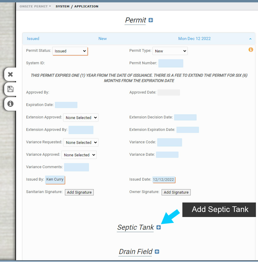
5. Next, add a new Septic Tank

6. Enter the following information about the Septic Tank.
- Type: Septic
- Capacity Gallons: 1500
- Primary Treatment Gallons Per Day: 480
Save your edits.
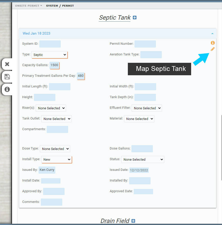
7. Select ‘Add to Map’ in the Septic Tank accordion to map the Septic Tank.
8. On the side pane menu, enter the Width and Length below and then select ‘Fixed Rectangle’.
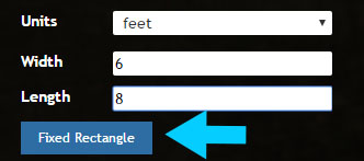
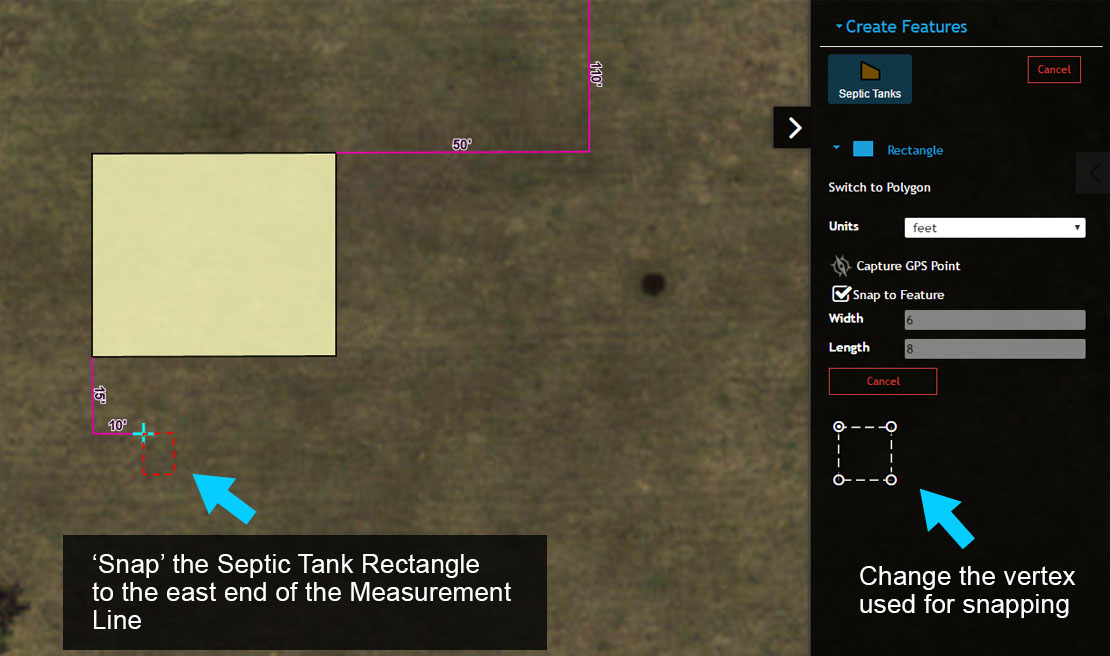
9. The Septic Tank needs to be mapped at the east end of the 10′ Measurement Line, so toggle snapping on and check the Rectangle Snapping reference (white dashed rectangle in menu) to see what vertex on the Rectangle will be used for snapping.
The default snap setting for a Rectangle is always the northwest corner, which works for this situation. You can always select a different snap vertex by clicking on it in the Rectangle Snapping reference.
10. Next move the Septic Tank so that the northwest corner is near the east end of the 10′ Measurement Line. Complete the Septic Tank by ‘snapping’ it to the Measurement Line.
Once the Septic Tank is mapped, the Form will open again. Save your edits and close the Form to continue.
Adding the Drainfield #
1. Following the same process used to add the Septic Tank, use the Permit Form to add a new Drainfield (System Information Form if not using Permitting).
Select System point > Scroll down to Permit Accordion and expand, scroll down to Drainfield and select ‘Add Drainfield’.
Enter the following information for the Drain Field
- Drain Field Type: Gravity Bed
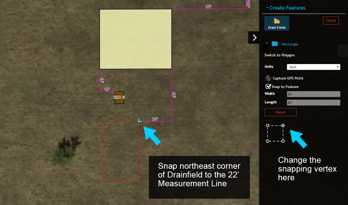
Drain Field – the northeast corner of a 24′ by 40′ Drain Field will be located 35′ south and 22′ west of the southeast corner of the Building. The 24′ segment of the Drain Field will be oriented east/west.
2. Map the Drain Field so its northeast corner is ‘snapped’ to the west end of the 22′ Measurement Line. Note that you will need to change the snapping vertex to accomplish this task.
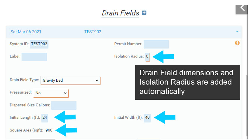
3. After mapping the Drainfield the Form will open.
Note the the dimensions of the Drain Field are automatically added to the Form, including the Width, Length and Square Feet. If you do not map the Drain Field, these values will need to be entered manually.
Mapping Laterals #
1. With the Drain Field in place, you can add Laterals or other wastewater lines to the map.
There are a number of ‘Septic Line’ types including Laterals, Septic, Trench and Other that can be mapped – each is listed on the Create Features menu.
In this example you will add Laterals to the Drain Field, so select Septic Lines (Lateral) from the Create Features menu.
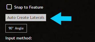
2. Select the ‘Auto Create Laterals’ tool to get started. There will be 8 Laterals for the Drain Field you mapped. Mapping all 8 Laterals one at a time is possible, but it would be very time consuming. To streamline mapping Laterals you will use the ‘Auto Create Laterals’ tool to automatically map Laterals in a Drain Field.
3. You will now see a new window titled ‘Septic Laterals Creation’ appear. The window will be used to guide you through the process of automatically adding Laterals to the Drain Field.
Start by selecting the Drain Field.
4. Once the Drain Field is selected the default settings of the number of laterals, on center spacing and orientation or side of origin will be displayed both on the map and in the ‘Septic Laterals Creation’ menu.
These are default settings that you will change to reflect the 8 Laterals running north/south in our Drain Field.
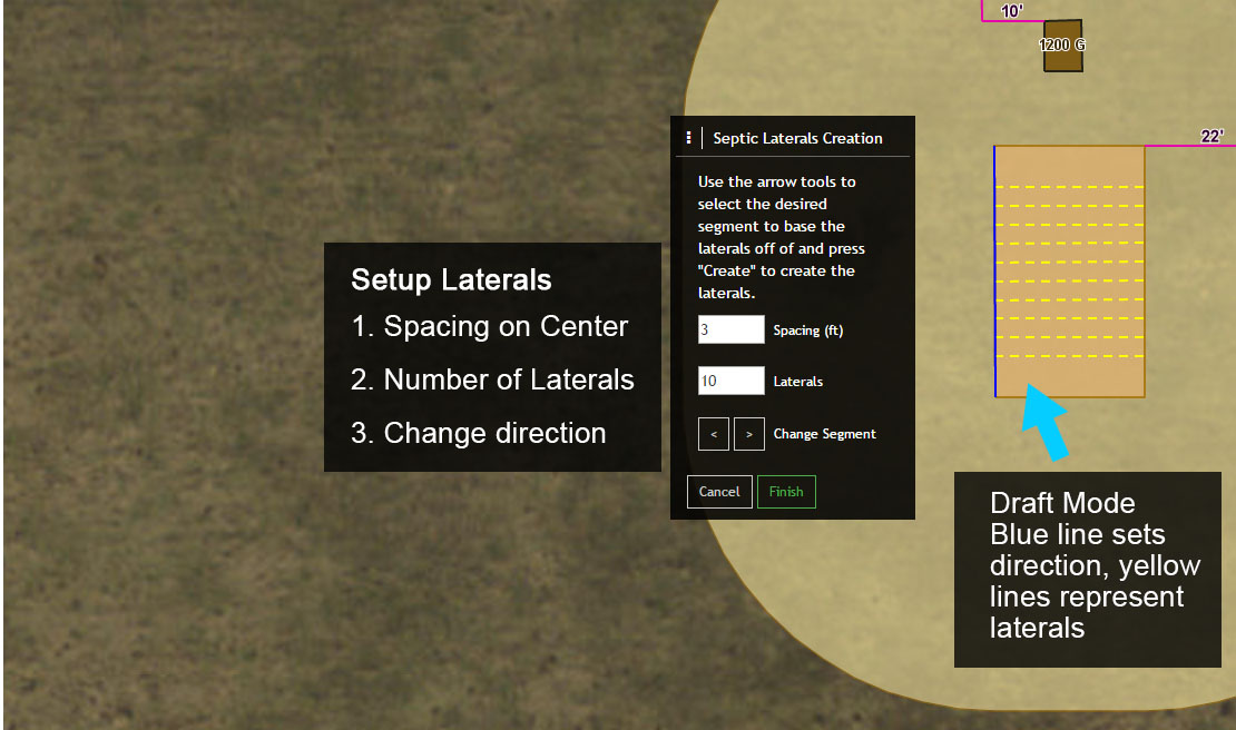
5. Next, experiment by modifying the spacing, number of laterals and by changing the segment that determines the direction of the Laterals.
You can change the spacing and number of laterals using the increment buttons or simply enter a new value.
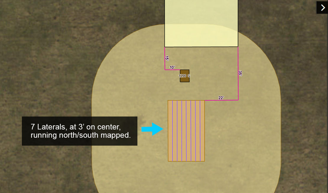
6. After experimenting, set the spacing to 3 (3′), the number of laterals to 8 and change the direction of the laterals to north/south.
Finally, select ‘Finish’ to complete the process. You may also map other Septic Lines, for example add a Septic Line (Septic) line from the Septic Tank to the Drain Field or back to the Building.
Note that the number of Laterals will automatically be added to the Drain Field and be displayed on the System Information Form.
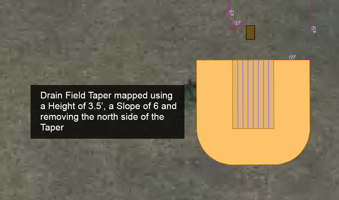
Mapping a Drainfield Taper #
1. Next, a Drain Field Taper will be added to the Drain Field. Start by selecting the Drain Field Taper from the Create Features Menu.
For this Drain Field there will be a slope on the Taper of 1:6 with a height of 3.5′.
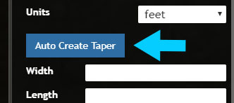
2. Similar to mapping Laterals, you will use the ‘Auto Create Taper’ tool to automatically map a Drain Field Taper. Select the ‘Auto Create Taper’ tool to get started.
3. You will now see a new window titled ‘Instructions’ appear. The window will be used to guide you through the process of automatically adding Laterals to the Drain Field.
Start by selecting the Drain Field.
4. Once the Drain Field is selected the default settings for Height and Slope will be displayed in the Instructions menu. There is also an option (House Side) to modify the Taper so that one side of the slope is not mapped.
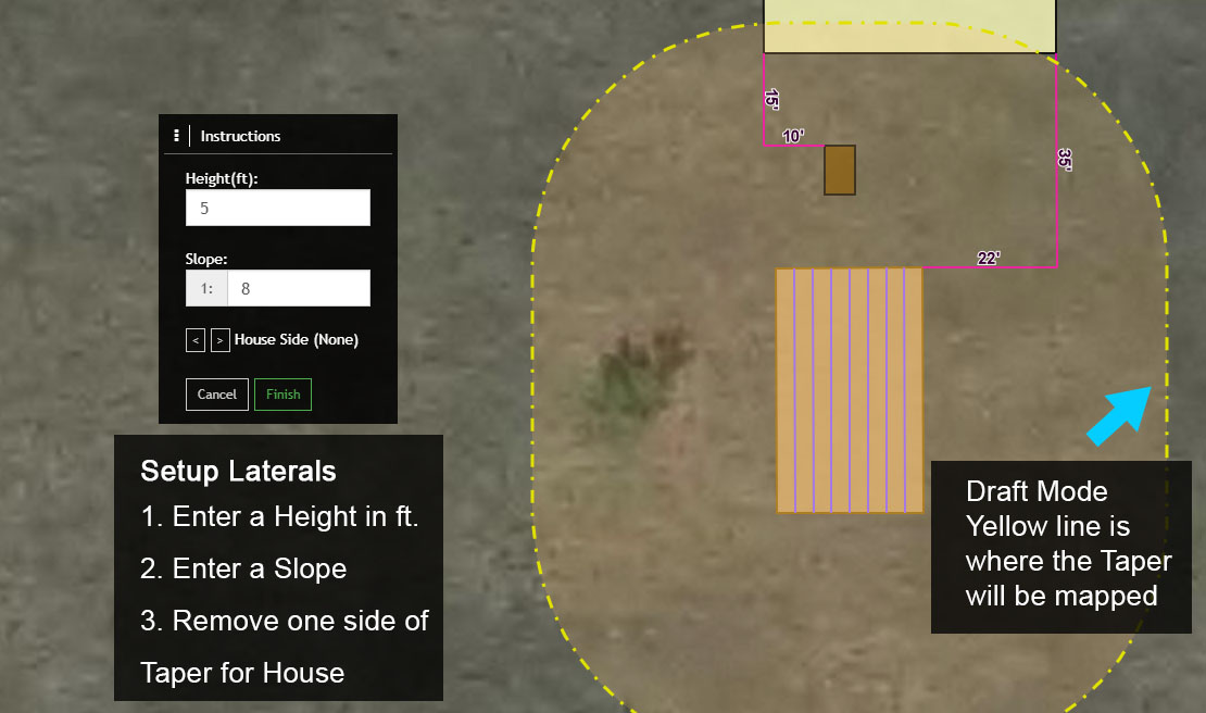
5. Next, experiment by modifying the Height, Slope, Sand Plateau and by using the House Side to modify the Taper.
6. After experimenting, set the Height to 3.5, the slope to 6 and remove the Taper on the north side of the Drain Field where it intersects the Septic Tank.
Finally, select ‘Finish’ to complete the process.
Adding Soil Borings #
The next mapping task will be to add Soil Borings to the map. Soil Borings include Soil Horizons, which are added after a Soil Boring has been created.
1. To get started select the System point and select ‘Show Form’ to open the Onsite Permit Form (System Information Form if not using Permitting).
Select ‘Edit’ to start an edit session.
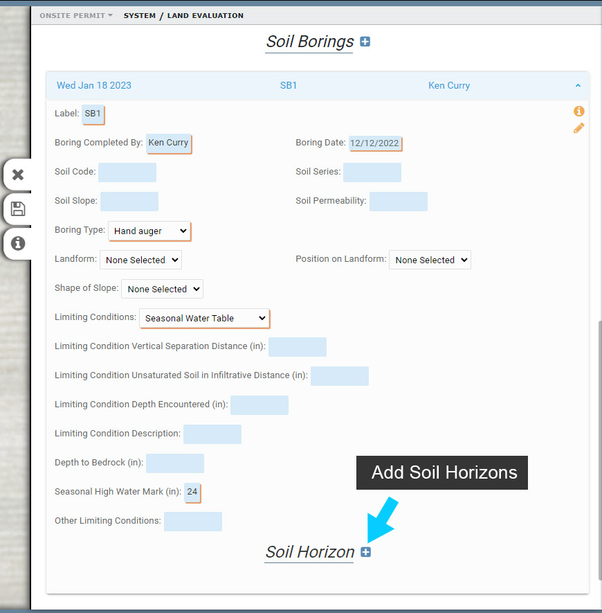
2. Scroll down to Soil Borings and select ‘Add to Soil Borings’ to create a new Soil Boring.
Soil Borings include general information and Soil Horizon information. When you add a Soil Boring, the Form displayed initially is used to enter Soil Boring information, such as who completed the boring, the date, seasonal high water mark and more.
Once the basic Soil Boring information is added to the Form, Soil Horizons can be added.
3. Enter the following base information for the Soil Boring:
- Label: SB1
- Boring Date: Current Date
- Seasonal High Water Mark: 24″
Once the Soil Boring information has been entered, select the ‘Add to map’ button and map the Soil Boring in or near the Drain Field.
Note that if you have the Soil Code, Soil Series and Soil Slope fields on your Soil Boring, they will automatically populate once the Soil Boring is mapped. FetchEH uses another map service to obtain these values, so if they do not populate the map service is non-responsive.
Adding Soil Horizons to a Soil Boring #
Once the Soil Boring has been added to the System and mapped, you can add Soil Horizons.
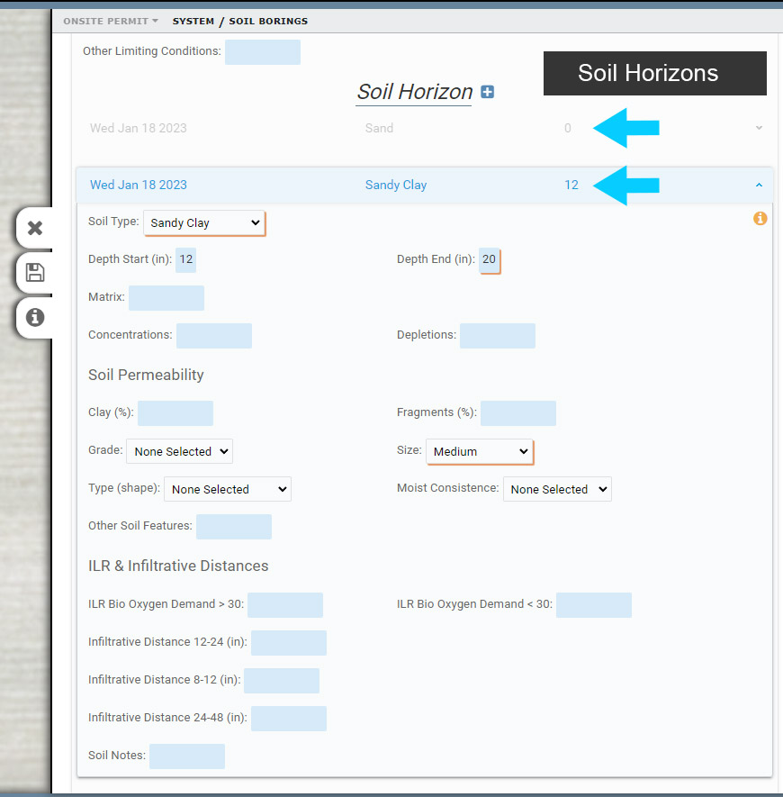
1. With the Form open and in ‘edit’ mode, scroll down to the Soil Boring > Soil Horizons and select ‘Add to Soil Horizon’ to create a new Soil Horizon.
2. Next, select a Soil Type and enter a Depth End of 12 for the first Soil Horizon (note Depths are in inches).
Note that the Depth Start is set to 0 as this is the first Soil Horizon.
3. Below the Depth Start and Depth End there are a number of characteristics that can be selected to further describe the Soil Horizon. Review these characteristics and select a Soil Type.
4. Add a second Soil Horizon.
Note that the next Soil Horizon will automatically populate the Depth Start to match the previous Soil Horizons Depth End, here 12.
Two Part Measurement Lines #
You can add as many Soil Borings to a System, and multiple Soil Horizons for a Soil Boring. Soil Horizons will be stacked in the Form when there is more than one. To view a collapsed Soil Horizon in a Form, select it and it will expand to display its contents.
Next, you will determine the distance between the Soil Boring and either the Elevation Mark or the Benchmark.
Even when not using GPS in the field, you can use the following option to quickly measure the distance between two features that are mapped, in this instance the Soil Boring and the Elevation Mark.
1. Start by selecting the Measurement Lines from the Create Features menu.
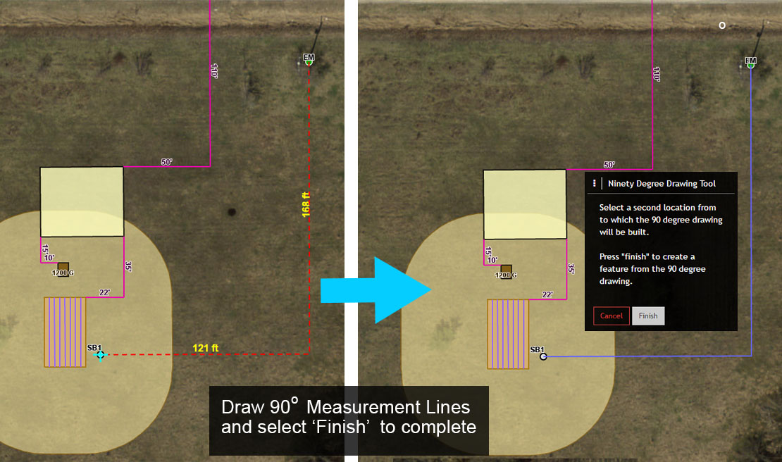
In this example the distance between the Soil Boring and the Elevation Mark is unknown, so you will use the ’90 Degree Angle’ tool to map two new Measurement Lines between each feature.
2. From the Measurement Lines menu, toggle on ‘Snap to Feature’ and then select ’90 Degree Angle’.
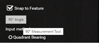
The ‘Ninety Degree Drawing Tool’ window should now be visible on the map. The window provides instructions and tools to draw two (2) Measurement Lines at a 90 Degree Angle to one another.
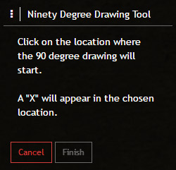
3. To start, move the cursor over the Elevation Mark and click to establish the starting point of the 90 Degree Measurement Line.
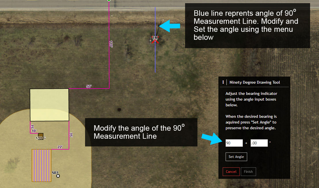
4. Once the starting point is established you will notice a red X with a blue line running through it. The red X marks the starting point of the 90 Degree Measurement Line, and the blue line indicates the initial angle of the line, which defaults to 0 Degrees.
The blue line also determines the direction of the first Measurement Line extending from the Elevation Mark. In this case, the first Measurement Line will extend either north or south from the starting point.
5. Use the Ninety Degree Drawing Tool menu to change the initial angle from 0 + .00 to 90 + .00. This will also change the direction of the blue line from north/south to east/west.
Next, select ‘Set Angle’ from the menu to continue.
6. You should now see two dashed red lines on the map with one line extending from the starting point (Elevation Mark), and the other line running perpendicular to the first.
Move the end of the second line to the Soil Boring and click. This will change the color of the two lines to blue.
7. Select ‘Finish’ from the 90 Degree Drawing Tool menu to finish mapping the two new Measurement Lines.
With the Edit Features menu open, review the Label, Recorded Length and Bearing fields. These values are automatically captured. The Recorded Length and Bearing values can’t be modified.
Note that the Label value is rounded and that the Label value can also be edited.